Star to delta wiring and energy distribution schema
Connection "star - delta" is commonly used for starting 3 phase motors and it is a mathematical technique to reduce high current of an electrical network. Reason for this is very high initial current at start of a 3 phase motors. Why is current very high upon start of a AC motor is something that we wont explain here, and more info you can find on wikipedia on this topic AC motor.
So lets back on Star-Delta wiring diagram and schema.
I wont write here a dissertation, I will just tell you some facts that you need to know. So initial current when you start motor can be ten times higher then motor actually use. So scientist and engineers found way to reduce this on some reasonable level and what they found is this start to delta wiring. You may or may not know that every 3 phase motor have 3 coils and those coils have two endings, so you have 6 terminals in box.
With this 3 coils you can form Star connection if you wire together all 3 endings U2,W2,V2 of every coil and on the other U1W1V1 end you'll need to connect phase (see picture above). So you will have this Star connection:
Initial current on this Star connection is much lower than initial current on Delta connection.
So the main point of usage is that you start motor with Star connection and after some period you reconnect motor to Delta connection and reduce stress of your electrical network.
This is a picture of delta connection:
You can see that in delta wiring you need to connect V1U2 with phase and on the pic you can see other endings so you can figure it yourself for the rest of wiring.
Why is initial current higher in delta than in star connection I will explain in other topic.
So you ask yourself how to reconnect motor from star to delta? Well for that operation you need three Contactors and I will explain to you how to wire them with motor and have full automated Start-delta start. Beside 3 conectors you will need a time relay too.
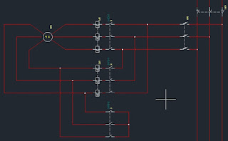
So lets start, here is schema for wiring:
Click on picture to see full size and lets explain:
Notice that this is now wiring for energy distribution, there is not command wiring on this schema. I will write about command part in other post so you can have full picture of everything. Here is link to Delta-Star command part.
As you can see on schema you have one main switch and fuses before 3 contactors. You must add this for security reasons. After fuses electric current come to contactors and here is a tricky part that you must know.
You can see that two of the contactors (their input terminals) are wired directly on phases and 3rd is wired in star on input terminals. The rest of the wiring with motor you can see from pic and here is whats happened with command of these three contactors.
On start, command current activate 1st and 3rd contactor so you have U1W1V1 connected with phases through 1st and U2W2V2 connected each other in star through 3rd contactor.
After some time, usually 5 to 7 seconds, command current deactivate 3rd contactor and activate 2nd while 1st contactor remain activated all the time. As result you have motor terminals connected as it is on Delta connection picture.
Just to make it clear those components marked on schema as KF are thermal protectors.
I hope I help you to understand how to do this with 3 contactors and in next article I will show you how to add command part to this and have full automated motor starter.


No comments:
Post a Comment