Star to delta command part explanation
As I mention in previous topic here we represent to you schema for command current or control current however you call it. For energy schema read this post Schema star-delta connection
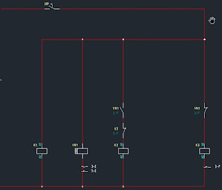
So here is picture of schema:
To make you clear up is phase and down is neutral. You can that we have use for this example 3 contactors, one switch for command/control current and one time relay.
On every contactor and time relay you have terminals A1 and A2 and these terminals is used to bring power to contactor coil. When you activate coil you switch energy terminals of contactor from "Open" position to "Closed" and you can control power distribution to the motor.
In this command schema you can see coil icons and phase to every is connected to A1 terminal and neutral is connected to A2 terminal of each component.
Let me explain how this system works:
- When you turn on command switch KP you bring power to coils of time relay VR1, 1st contactor K1 and to 3rd contactor K3.
- First K1 contactor is controlled only by command switch so when you "switch on" this contactor will close his terminal and bring power to U1,W1 and V1 motor terminals.
- Second K2 contactor will remain "open" until time relay activate him.
- Third K3 contanctor will also be activated at start of process because command current to A1 terminal come through NC contact of time relay. NC means normal closed so this contact is closed until time relay respond. As result you have Star connection on motor.
- Time relay have NC and NO contacts and it is usually set to 5-7 seconds delay time. When you turn on main switch he starts counting. NC contact is close for this period and another NO (normal open) is open so contactor K3 get power while K2 is turned of.
When time relay react NO contact gets closed and NC contact goes to "Off" position. As result contactor K3 lose power and K2 get energized and you have Delta connection on motor.
You can see that I add one more NC contact above K2 coil. This is NC contact from Contactor K3 and his purpose is to prevent any possible damage is for some reason any of K2 or K3 fails and stays in "closed" position.
For example if K3 fails and remains on while time relay activate K2 you will have short circuit on all phases. That why you add this in your command circuit and if K3 fails then time relay cant activate K2.
I hope this helps you, for any questions use comment section.


No comments:
Post a Comment